Lighttools 2024.03
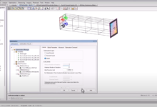
LightTools illumination simulation software supports virtual prototyping, lighting simulation, optimization, and photore...
LightTools illumination simulation software supports virtual prototyping, lighting simulation, optimization, and photore...
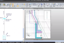
ISTRAM ISPOL 2024 is the most comprehensive and efficient application in the market to design civil engineering projects...
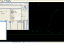
EasyPower is a software tool used for design, analysis, and optimization of electrical power systems. Widely used by des...
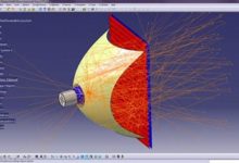
LucidShape CAA V5 Based is an interactive development environment for optical simulation and analysis integrated into th...
Chesapeake’s SonarWiz processing software streamlines the survey process and simplifies the number of software programs ...
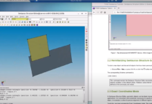
Technology computer-aided design (TCAD) refers to the use of computer simulations to develop and optimize semiconductor ...
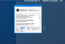
What’s New in GibbsCAM 2024 Powerfully Simple, Simply Powerful GibbsCAM 2024 continues to boost end-user productivity fo...
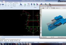
Cadmatic ship design software solutions improve your design, engineering, and production processes. Your user experience...
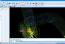
CDEGS The most powerful and accurate suite of commercially available grounding (earthing) and electromagnetic analysis s...
Synopsys’ CODE V optical design software provides industry-leading solutions for lens design and other imaging sys...